FC006 - iRobot Roomba Virtual Wall
iRobot sells autonomous Vacuum cleaners Roomba. They have IR receiver to detect obstacles and to receive remote control commands. iRobot sells a “virtual wall” 40€ to create a border in order to constraint the robot in a part of the room to clean. Hardware parts cost les than 10€ ! I decided to create my own, based on ATtiny AVR microcontroller.
You can find links to the related video recordings and printable materials at the end of this post.
Video
Hardware
I took the schematic from Petezah’s repository. I removed the external resonator to save some power as I don’t need a precise timing and slightly changed some components.
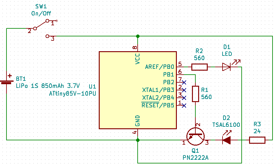
I used a regular switch to power the wall, thus I can completly switch it off and save the battery.
The ATTiny13 would be a good candidate, but the Flash size would require strong code optimizations. I chose an ATTINY85 despite it is oversized, because I ordered 5 of them (I can frie one during the dev and tests) and it is versatile enough to be reused in other projects. I chose the “ATTiny85V-10” because “V” means that it can work with lower voltage, down to 1.8V (last longer when the batteries are low and when there is no voltage booster) ; only 10Mhz because my provider did not have 20Mhz anymore and this project will run at 1Mhz to save power and lower the voltage requirements.
BOM
| Item | Qty | Cost |
|---|---|---|
| ATTINY85V-10PU | 1 | 1,38 € |
| IR LED 5mm, 940nm, 10°, 100mA | 1 | 0,35 € |
| Red 5mm LED | 1 | 0,07 € |
| DIP8 seat | 1 | 0,15 € |
| 2N2222A Transistor | 1 | 0,19 € |
| 560 Ohms Resistor | 2 | |
| 24 Ohms Resistor | 1 | |
| LiPo 1S 3.7V 850mAh | 1 | 5.52 € |
| TP4056 Micro USB LiPo Charging Protection Board TE585 | 1 | 1.27 € |
Alternative A : with AA batteries
| Item | Qty | Cost |
|---|---|---|
| 2X 1.5V AA Battery Holder | 1 | 3.61 € |
Alternative B : with CR123A 3V battery
I chose to use the 1S/850mAh LiPo with the charging PCB because I had it in my drawers, thus the enclosure and the source code (voltage thresholds) are designed for the LiPo.
Software
ATtiny compiler for Arduino
The Arduino IDE’s default repositories do not include the “ATTiny” board, thus I had to add the following repository in the Edit/references dialog.
http://drazzy.com/package_drazzy.com_index.json
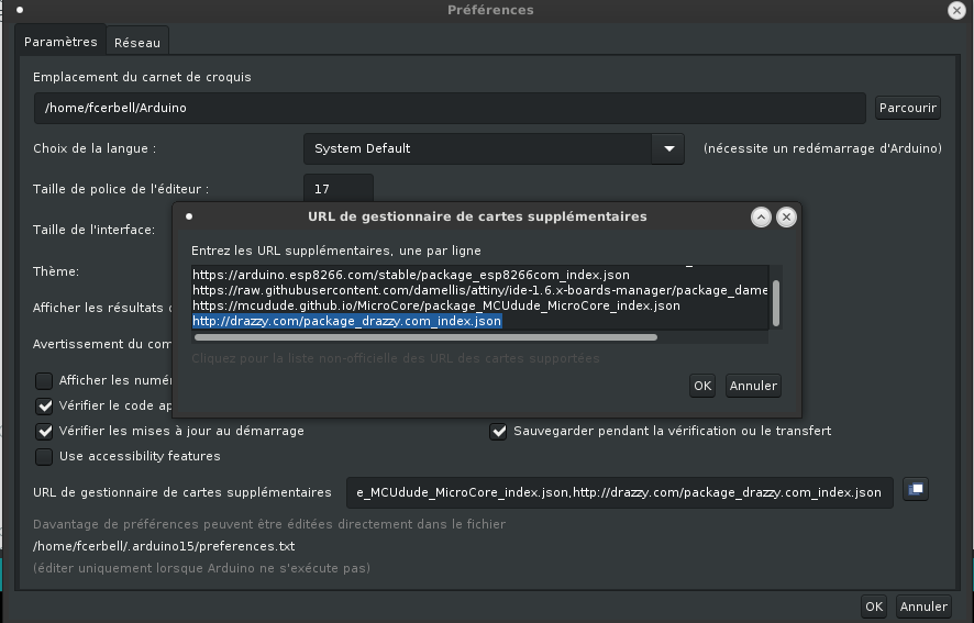
Then, I was able to add the ATTinyCore by Spence Konde in the board manager.
This core can burn the MCU fuses to change the frequency and other settings.

I used an USBasp programmer and connected it to the ATTiny’s ICSP (SPI) pins, and I chose the relevant choice in the Tools/Programmer menu. Thus I can burn a bootloader, I can program the fuses and I can upload the bits.
I made the following settings in the Tools menu :
- Board : ATTiny25/45/85
- Chip : ATTiny85
- Clock : 1 Mhz (internal)
- BOD Level : BOD disabled
- Save EEPROM : EEPROM retained
- Timer 1 clock : CPU
- LTO : Enabled
- millis : Enabled
BOD is disabled because I don’t care if the voltage drops too low and crashes the device. I also disable it in the source code, but if it is not disabled in the fuse, it will be resetted and restarted after each sleep, will consumme power and will take time. I could also remove the millis support and save few bytes, but my compiled program will never use more than 15% of the Flash, thus I don’t need to disable it.
Clock has mandatory to be internal otherwise, you’ll brick you MCU
These settings can be burned in the fuse now, using the Tools/Burn bootloader menu, but I don’t need because they will also be automatically updated when I upload the sketch in the Flash using the USBasp programmer.
Transmission protocol
Each Roomba command is a 8bits char. Each bit is encoded with the following pattern, using a 38kHz carrier.
- 1 = 3ms high followed by 1ms down
- 0 = 1ms high followed by 3ms up
Each command needs to be sent 3 times with a 100ms break between each and 150ms after the last repeat. Thus, sending a command last approximately \(3 * ( 32ms + 100 ms) + 50 ms = 450 ms\)
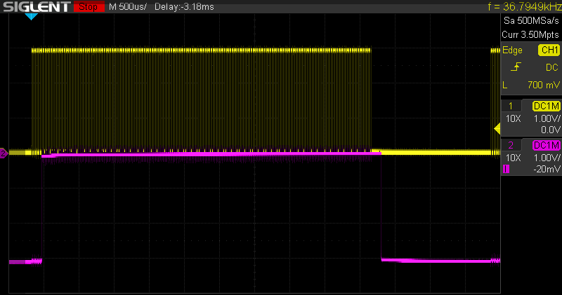 PB0/Pin6 output in yellow, received signal from a VS1838 IR decoder
Timer0 programmation
I used low-level programmation to generate 38kHz / 50% duty PWM from the timer
- This carrier will encode the signal by connecting/deconnecting it to the ATTiny’s PB0 pin (pin 6). I had to disable Timer0’s generated interrupts because Arduino libs have an interrupt handler (to manage the milli and delay functions) connected to it and it would also wake up the MCU too early during sleep cycles.
// PWM Carrier
// FastPWM-Compare mode, no prescale (to support 1MHz internal clock)
// Disable interruptions (Arduino libs have ISR for delay and millis)
#define PWM_SETUP(val) ({ \
    const uint8_t pwmval = SYSCLOCK / val / 1000; \
    TCCR0A = 1<<WGM00 | 1<<WGM01; \
    TCCR0B = 1<<WGM02 | 1<<CS00; \
    TIMSK &= 0b10000001; \
    OCR0A  = pwmval;\
    OCR0B  = pwmval/2; \
  })
#define PWM_ON  ({TCNT0=0; TCCR0A |= _BV(COM0B1);})
#define PWM_OFF (TCCR0A &= ~(_BV(COM0B1)))
Delay and timing
Timer0 is used by Arduino’s delay function, this function is not useable anymore because I changed its frequency. I reused the TV B Gone approach : a busy loop on NOP instruction. I tuned it with my oscilloscope, it depends on the internal ATTiny85 clock (set to 1 Mhz).
// Busy loop to manage very small delays (<16ms) that
// can not be managed by wdtSleep timer
// Inspired by TV B Gone project
// TODO: use Timer0 (38kHz), SLEEP_MODE_IDLE and interrupt
//       if not too long for PWM signal generation
#define DELAY_CNT SYSCLOCK/1000000
#define NOP __asm__ __volatile__ ("nop")

void delay_ten_us(unsigned long us) {
  uint8_t timer;
  while (us != 0) {
    for (timer = 0; timer <= DELAY_CNT; timer++) {
      NOP;
      NOP;
    }
    us--;
  }
}

void custom_delay_usec(unsigned long uSecs) {
  delay_ten_us(uSecs / 10);
}
Long breaks and powersaving
For all the 100 ms and 150 ms breaks, I can not use a busy loop, it would drain
the battery. I put the device in the deepest level of sleep :
SLEEP_MODE_PWR_DOWN. In this mode, only a physical interrupt or the watchdog
timer can wake it up.
The Watchdog can be configured with $2^n16 ms$ timeout, ($0<=n<=9$), basically, not less than 16 ms, not more than 8s. I made a loop to have several sleeping cycles with relevant timeouts to be as close as possible from the required sleeping time. I had to program it low-level to disable the *reset function and enable the interrupt function only.
I could avoid disabling the BOD because it is supposed to be disabled by the fuses. Furthermore, I disable all interruptions all the time, but I enable them only before going to sleep. I don’t want to sleep forever. I wrote the program to not rely on any interruption (no puch button, no delay, no millis, nothing) and I can disable all of them most of the time (when not sleeping) to keep my timings under control.
I need to disable Timer0, because it is useless to generate the 38kHz carrier during sleep and would consume some current. Everything else is already disabled (ADC, Timer1).
// watchdog interrupt
ISR (WDT_vect) {
  wdt_disable();
}

void wdtSleep (unsigned int ms) {
  power_timer0_disable();
  set_sleep_mode (SLEEP_MODE_PWR_DOWN);
  ms = ms / 16;
  // 0: 16 ms, 1: 32 ms, 2: 64 ms, 3: 128 ms, 4: 256 ms,
  // 5: 512 ms, 6: 1024 ms, 7: 2048 ms, 8: 4096 ms, 9: 8192 ms,
  unsigned char wdp = 0;

  while ((ms) && (wdp <= 9)) {
    if (ms & 1) {
      MCUSR = 0;                              // clear various "reset" flags
      //      noInterrupts();                         // Timed sequence follow
      WDTCR = (1 << WDCE | 1 << WDE);         // watchdog change enable
      WDTCR |= (1 << WDIE | 0 << WDE | wdp) ; // enable wdt interrupt
      //      interrupts();      // End of timed sequence

      // turn off brown‐out enable in software
      MCUCR = bit (BODS) | bit (BODSE);
      MCUCR = bit (BODS);

      wdt_reset();
      interrupts();      // waiting for watchdog interrupt to wakeup
      sleep_mode ();
      noInterrupts();    // no need for interruptions in this sketch
      sleep_disable();
    }
    ms = ms >> 1;
    wdp = wdp + 1;
  }
  power_timer0_enable();
}
Activity LED and power status
I make the activity LED blink quickly once every 15 seconds approximately, twice when the battery voltage falls below a first threshold and three times when it falls below a second threshold. The thresholds depend on the battery type, on the ATTiny85 version (V or not V) and the CPU frequency.
- regular batteries (2xAA, CR123A, CR2032) : 2V/1.8V for ATTiny85
- LiPo with BMS : 3V/2.8V
For this, I reused the smart ReadVcc function from the
MySensors1 project, I only disable the ADC after reading and
enable it before. Thus, the ADC is disabled most of the time.
long readVcc() {
  power_adc_enable();
  // Read 1.1V reference against AVcc
  // set the reference to Vcc and the measurement to the internal 1.1V reference
#if defined(__AVR_ATmega32U4__) || defined(__AVR_ATmega1280__) || defined(__AVR_ATmega2560__)
  ADMUX = _BV(REFS0) | _BV(MUX4) | _BV(MUX3) | _BV(MUX2) | _BV(MUX1);
#elif defined (__AVR_ATtiny24__) || defined(__AVR_ATtiny44__) || defined(__AVR_ATtiny84__)
  ADMUX = _BV(MUX5) | _BV(MUX0);
#elif defined (__AVR_ATtiny25__) || defined(__AVR_ATtiny45__) || defined(__AVR_ATtiny85__)
  ADMUX = _BV(MUX3) | _BV(MUX2);
#else
  ADMUX = _BV(REFS0) | _BV(MUX3) | _BV(MUX2) | _BV(MUX1);
#endif
  custom_delay_usec(2000); // 2ms enough

  ADCSRA |= _BV(ADSC); // Start conversion
  while (bit_is_set(ADCSRA, ADSC)); // measuring

  uint8_t low  = ADCL; // must read ADCL first - it then locks ADCH
  uint8_t high = ADCH; // unlocks both

  long result = (high << 8) | low;

  result = 1125300L / result; // Calculate Vcc (in mV); 1125300 = 1.1*1023*1000
  power_adc_disable();
  return result; // Vcc in millivolts
}
Roomba commands
I rewrote the roomba_send function to make it more compact and specialized.
void roomba_send(char code) {
  for (char i = 7; i >= 0; i--) {
    if (code & (1 << i)) {
      PWM_ON;
      custom_delay_usec(3000);
      PWM_OFF;
      custom_delay_usec(1000);
    } else {
      PWM_ON;
      custom_delay_usec(1000);
      PWM_OFF;
      custom_delay_usec(3000);
    }
  }
}
I found the list of commands in Probonopd’s gist2 and in iRobot Roomba 500 Open Interface Specs, page 223
 IR Remote Control
 129 Left
 130 Forward
 131 Right
 132 Spot
 133 Max
 134 Small
 135 Medium
 136 Large / Clean
 137 Stop
 138 Power
 139 Arc Left
 140 Arc Right
 141 Stop

 Scheduling Remote
 142 Download
 143 Seek Dock

 Roomba Discovery Driveon Charger
 240 Reserved
 248 Red Buoy
 244 Green Buoy
 242 Force Field
 252 Red Buoy and Green Buoy
 250 Red Buoy and Force Field
 246 Green Buoy and Force Field
 254 Red Buoy, Green Buoy and Force

 Roomba 500 Drive-on Charger
 160 Reserved
 161 Force Field
 164 Green Buoy
 165 Green Buoy and Force Field
 168 Red Buoy
 169 Red Buoy and Force Field
 172 Red Buoy and Green Buoy
 173 Red Buoy, Green Buoy and Force Field

 Roomba 500 Virtual Wall
 162 Virtual Wall

 Roomba 500 Virtual Wall Lighthouse ###### (FIXME: not yet supported here)
 0LLLL0BB
 LLLL = Virtual Wall Lighthouse ID
 (assigned automatically by Roomba
 560 and 570 robots)
 1-10: Valid ID
 11: Unbound
 12-15: Reserved
 BB = Which Beam
 00 = Fence
 01 = Force Field
 10 = Green Buoy
 11 = Red Buoy
All together
At the end, the setup and loop functions are quite simple :
void setup() {
  noInterrupts();  // no need to interrupt when not sleeping
  LED_SETUP;
  IR_SETUP;
  PWM_SETUP(38);   // 38kHz carrier
  power_timer1_disable();
  power_adc_disable();
  wdt_disable(); // In case it was rebooted during sleep, for any reason, without power cycle, wdt is still enabled
}
Similarly to iRobot’s original wall, I had to put a timeout when you forget to switch it off. It will go to an endless deepsleep after 150 minutes.
void loop() {
  iter++;
  timeout++;

  if      (iter == 1) bat = readVcc();
  else if (iter == 2) LED_ON;
  else if (iter == 3) LED_OFF;
  else if ((iter == 4) && (bat < 3000)) LED_ON;   // Thresholds in mV for 1S LiPo + BMS
  else if ((iter == 5) && (bat < 3000)) LED_OFF;
  else if ((iter == 6) && (bat < 2800)) LED_ON;
  else if ((iter == 7) && (bat < 2800)) LED_OFF;
  else if (iter == 120) iter = 0;                 // New battCheck every 15s approx

  roomba_send(code); // 4ms
  wdtSleep(100);     // 100 ms

  // Extra 50ms break every 3 burst to have a 150ms break
  if ((iter % 3) == 0)
    wdtSleep(50);    // 50ms

  if (timeout == 0) {
    set_sleep_mode (SLEEP_MODE_PWR_DOWN);
    power_all_disable();
    noInterrupts();
    sleep_mode();
  }
}
Enclosure
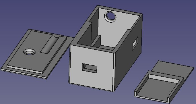
When we talk about home-automation, the most important criteria is the WAF (Wife Acceptance Factor)4 and the enclosure needs to be WAF compliant ! Thus, I designed the smallest enclosure as possible mainly depending on the battery form factor. It is designed to be small, stable, narrowing the IR beam, letting the charging/charged/activity LEDs to be visible, with the power switch at the rear and the micro-USB charging plug on the side.
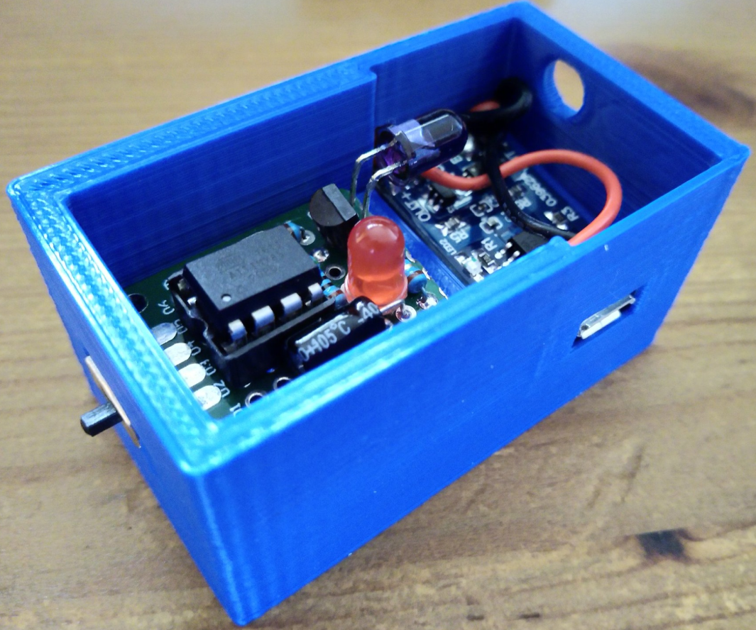
I included a spacer between the LiPo and the PCB to avoid any component pin hurting the battery, this would ignite the battery and would definitely not be WAF.
I designed the enclosure using FreeCAD, and exported each of the three bodies to a separate STL file. I printed them in PLA on my CR-10 printer with a 0.2mm quality and 20% infill using Cura.
Improvements
They are related to the autonomy and power saving. I measured 6mA average, thus the device should work several weeks or month with a 850mAh LiPo discharge curve, thus I kept these idea but did not implement them.
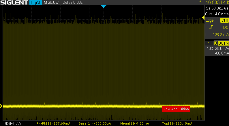 Current drawn (base current, spikes for activity LED and dark yellow for
constant signal emission)
Code
Use SLEEP_MODE_IDLE or better during the 1 and 3ms wait, probably by reusing
the 38kHz Timer0.
Hardware
Use a momentary push button to generate an interrupt, wake-up the wall and set a timeout : one press/one blink/one hour, 2 presses/2 blinks/2 hours, 3, 4, 5 and back to 1.
Home-automation
Thus, it becomes possible to enhance this project and use the MySensors project to implement a very smart “lighthouse” driven by the home-automation system.
Special thanks
The iRobot company for their amazing devices, their wonderful open specification and their learning kit.