Iot sensor on ESP8266 sending values to Redis
• •


Create a light sensor using an ESP8266 and an LDR for 5€, directly send the measures to a Redis database via a Wifi/TCP/IP stack and publish a push notification to notify your frontend user interface (described in a future blog post) that there is a new value to display in realtime. Redis is an in-memory key-value store with persistency to disk, high-availability and clustering. It is so easy to use that a simple micro-controller, such as an Arduino or an ESP8266, with a TCP/IP stack can connect and use it.
You can find links to the related materials at the end of this post.
Prerequisites
Hardware
I had to build about 200 such devices, for the cheapest price, within as short time as possible. The idea was to build these devices and teach how to use them with Redis in our French Redis meetups. The attendees can keep the device after the meetup to continue to play with it at home.
It had to be as cheap as possible (reached less than 5€), as easy and fast to build as possible (30 seconds less per device is important when building 200 of them), as versatile as possible to connect other sensors (thermistors, digital sensors, I2C sensors, SPI sensors, …).
First of all, you need some hardware. Despite I am an Arduino addict it would require a Wifi shield (expensive) and some soldering (longer to build). I chose to use a small breadboard, an all-in-one ESP8266, a resistor and an Light Dependent Resistor (LDR or photoresistor), that can be easily replaced with a thermistor for the same price.
Parts and tools
Lets talk about furnitures :
 Full size
My prices have a discount because I ordered more than 100 of each.
| Qty | Item | Price (€) | Link |
|---|---|---|---|
| 1 | 170 points breadboard | 0.86 | Banggood |
| 1 | ESP8266 ESP-12E/F breakout | 3.18 | Banggood |
| 1 | 10K Ohms resistor (metal or carbon) | 0.03 | Conrad |
| 1 | GL5528 LDR | 0.02 | Banggood |
| 1 | Micro-USB cable | 1.10 | Banggood |
| Total | 5.19 |
- Noze plier
- Cutting plier
Build
Here are the steps. Links are opening detailled pictures of steps.
-
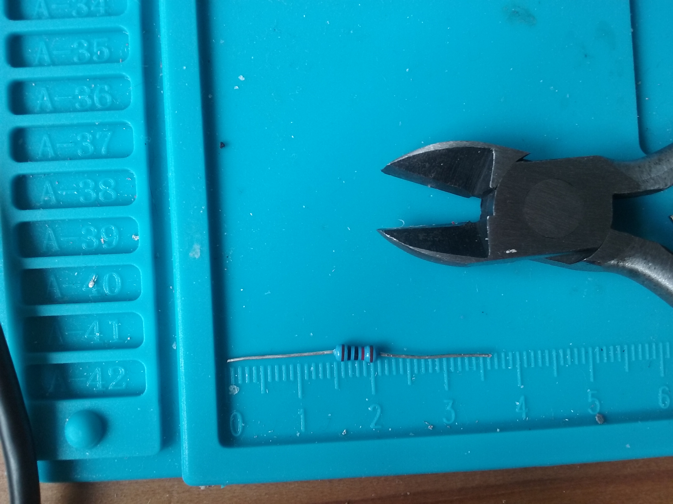
First, use the cutting plier to shorten the resistor legs. Shortenned resistor picture
-
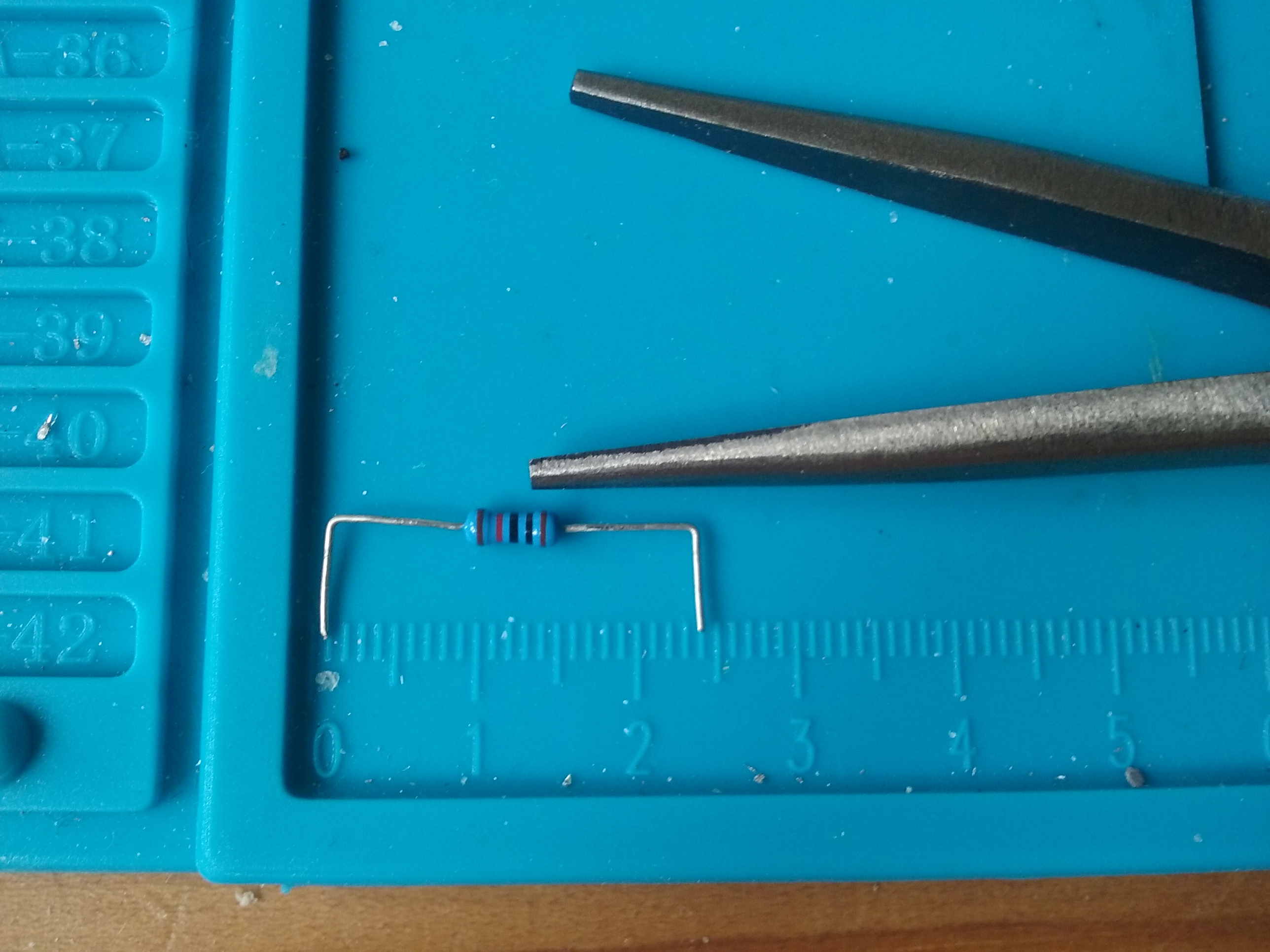
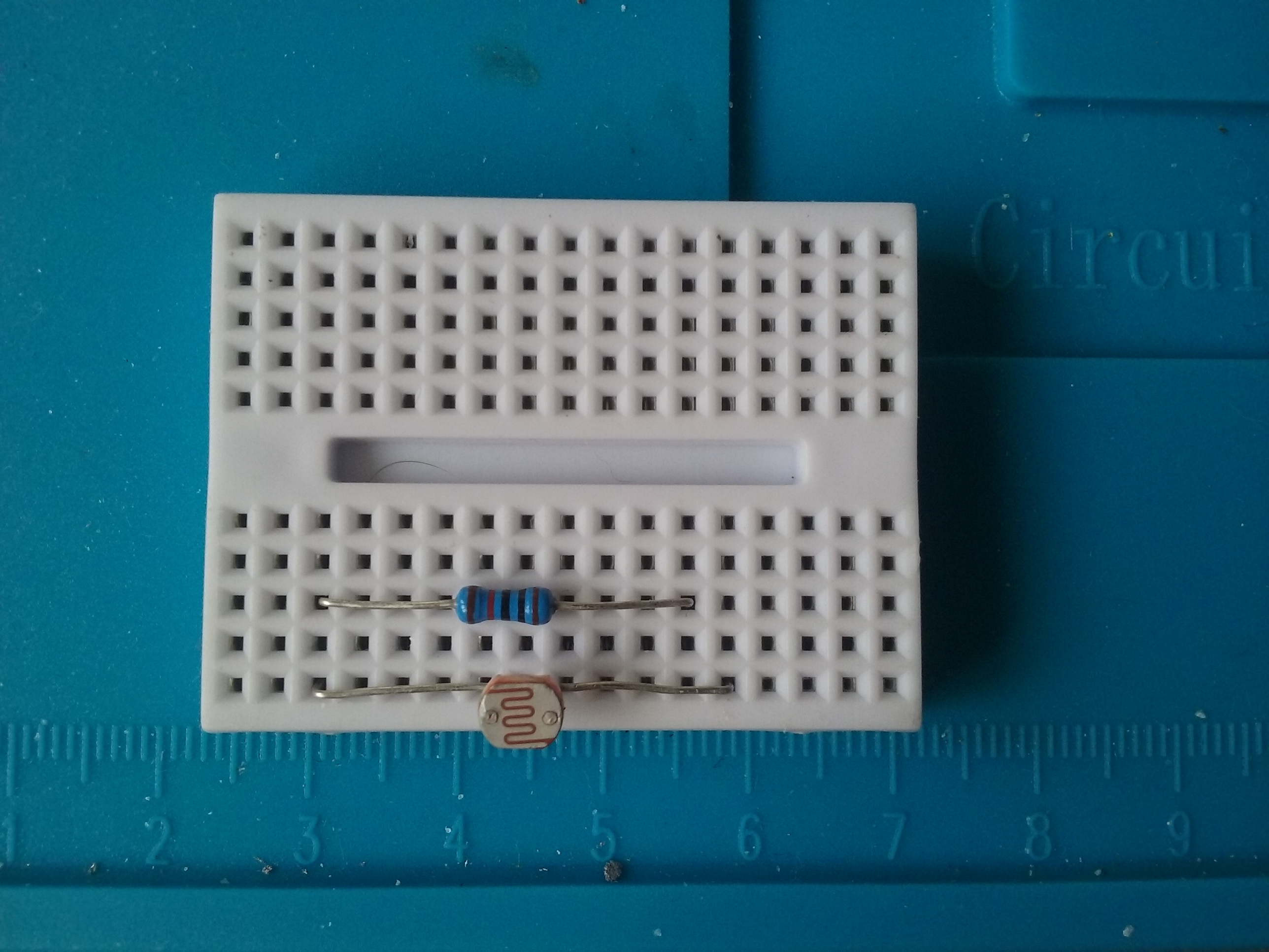
Fold the resistor legs to cross 9 holes (2.29cm) Folded resistor picture
-
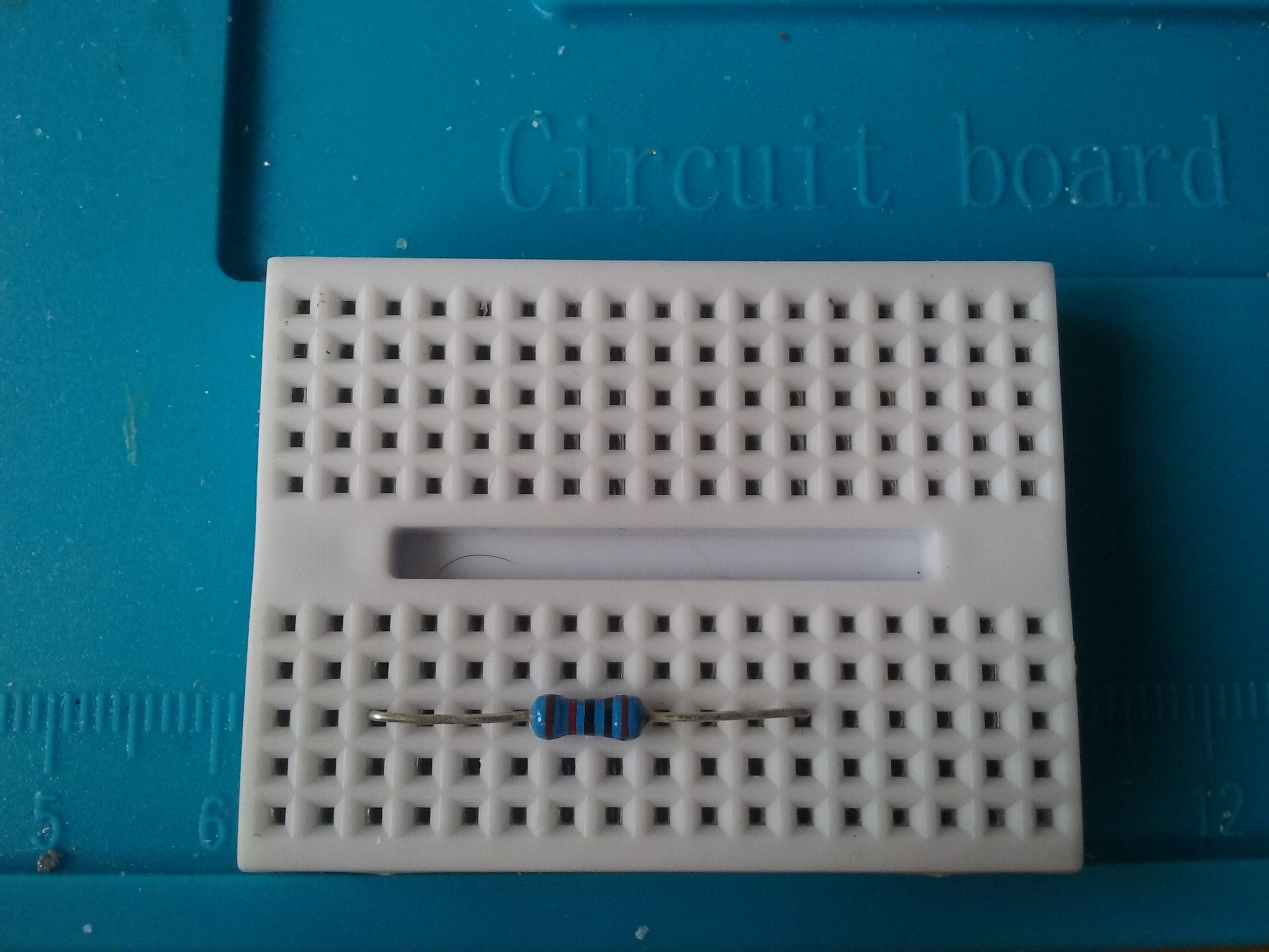
Place the resistor between C3 and L3 on the breadboard. Placed resistor picture
-
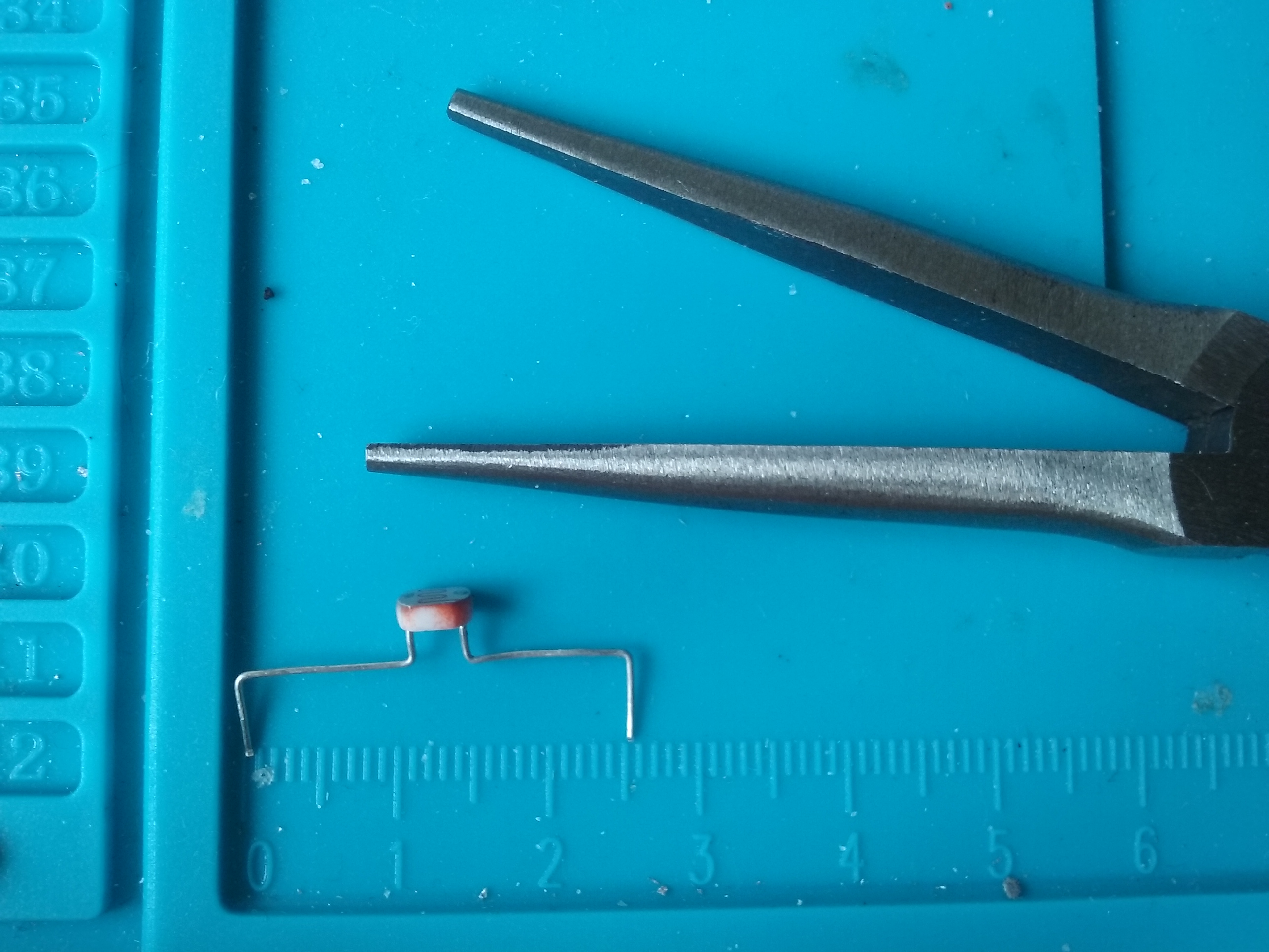
Cut the LDR legs to 2cm each. Shortenned LDR picture
-
Fold the LDR leds to cross 10 holes (2.54cm) Folded LDR picture
-
Place the LDR between C1 and M1 Placed LDR picture
-
Place the ESP breakout in order to have the AD0 pin in C2 and the 3.3V pin in M2 Placed ESP picture
-
Press gently and keep the LDR outside !!! ;)
 Full size
Congratulations !!! That’s ok for the hardware !
Software
IDE, cross-compiler and upload
We will need the software to write our code, the IDE, the software to compile our code which depends both on the combination computer/OS and targetted micro-controller, the cross-compiler, and the software to upload the compiled code to the device.
There are several IDE and toolchains available to compile C/C++ code for microcontrolers. I chose to use the very simple but sufficient IDE provided by the Arduino project. It is generic, but can automatically download the cross-compiler that runs on your computer to compile for your target device and it can also download and include a lot of helper libraries from internet repositories.
You can either go the the Arduino website to download the IDE1 or click on the direct download links :
Extract the archive in a folder anywhere in your filesystem. The IDE will be executed from this folder and all your files will reside inside this folder. The folder can be moved anywhere anytime.
Libraries, code sample and IDE Customization
The IDE can be customized to be portable and have everything in a single folder (the IDE itself, the configuration, the toolchains for the devices and your code). We only need to create a portable subfolder that will host all your code, all your libraries and your IDE configuration file (like some kind of home directory).
I prepared one and created a configuration file with the external repositories. As said previously, a cross-compiler toolchain needs to be installed. As the binaries depend on your computer and OS, I can only preconfigure the repository from which you’ll have to download and install them by youself. A Redis helper library and an empty code template are also included in the customization file.
The file will also add the full source code of this blog in your sketchbook.
-
Download the portable archive
-
Extract the archive at the top level of your IDE folder (or in the Contents/java subfolder for MacOSX users).
-
Start the IDE
-
Go to the Tools/Board/Board manager menu

-
Search for ESP8266 (there should be one found from the preconfigured repository), select it in the list and install it.

-
Close the dialog, and select the Tools/Board/NodeMCU 1.0 (ESP-12E Module) in the menu

You’re done with the IDE installation and configuration.
Redis
You need a Redis database, it can either be the community or the enterprise edition. This blog post will not tell you how to implement the sentinel protocol, nor the cluster API, respectively needed for high-availability and for clustering in the community edition. These two protocols are not needed for high-availability and clustering in the enterprise edition, these features will be automatically enabled if using the enterprise edition.
Given that the enterprise edition is seen as a single Redis instance by the applications, regardless if there is sharding and/or replication behind, and in order to keep this post not too long, I’ll describe the Redis community installation, without clustering or high-availability, and use it.
To avoid admin permissions requirement, to keep Redis portable and to master the used version, I will not use the pre-packaged redis server available in most of the Linux distributions repositories, but I’ll download, compile, configure and run the Redis version available on the official Redis community homepage .
Download the source code from the following link Redis source and
unzip it in a folder. Open a terminal inside this folder and type make. Once
the compilation is complete, run Redis from here without installing it in your
system, by typing ./src/redis-server --protected-mode no (without turning off
the protection, you will only be able to connect from localhost).
You’re done with Redis. Amazing, isn’t it, only four commands (download, extract, build and execute) and you have an up-and-running portable installation.
Micro controler application
Now, it is time to start coding!
Create a new application
You should have an empty application skeleton in your IDE when you start it.
Basically, there are two mandatory functions : void setup() and void loop().
When you reset it (either hard reset with the button, from the USB connection,
by powering it or soft reset from the application), it executes the
Arduino bootloader. if data is available on the serial link (bridged
with the USB connector), it stores the data in the flash memory and
execute the program from flash. If there is no data, the bootloader
directly executes the program from flash memory.
At each power cycle or reset, the program executes once the setup function and
then iterate on the loop one, endless.
So, you need to initialize the serial console (for debugging) and open a Wifi
connection from the setup function. Then, at each loop iteration, you will
check if you need to read the sensor’s value and send it to Redis, if
yes, you will check that you have an active connection to Redis and
open it if needed, and you’ll send your data.
Check sensors values
First, initialize the feedback with the serial console and read the sensor’s values.
In the setup function, initialize the serial console, wait for its
initialization (only useful for some Arduino such as the Yun, but
without drawback on others).
void setup() {
  // Serial console initialization for debugging
  Serial.begin(115200);
//  Serial.setDebugOutput(true); // Wifi debugging
  while (!Serial);
  Serial.println("Serial initialized.");
}
In the loop function, print the sensor’s value, from the
Analog-Ditial-Converter, to the serial console.
void loop() {
    Serial.print("Sensor value (0-1024) : ");
    Serial.println(analogRead(0));
}
Test your sketch with the tick icon in the toolbar, or from the menu Sketch > Verify/Compile or with the keyboard shortcut Ctrl+R.
If you have no error, upload it to the device using the arrow icon, the menu Sketch > Upload or the shortcut Ctrl+U. As soon as it is uploaded, it is executed.
Start the serial monitor with the right magnification glass icon, from the menu Tools > Serial Monitor or with the keyboard shortcut Ctrl+Shift+M. Choose the same baud rate as in the sketch (115200) and observe.
You can see the speed of the loop function. Despite you could introduce a
void delay(long ms) call in the loop, it would be a bad practice, the loop
function needs to be executed as fast as possible, without blocking,
this is the main event loop. It is better to initialize a millisecond
timestamp at each print and to only read a new value after a timeout :
//  your network SSID (name)
#define WIFI_SSID "YourWifiNetwork"
#define WIFI_PASS "YourWifiNetworkPassword"

#include <ESP8266WiFi.h>

unsigned long lastSensorRead=0;
void loop() {
  if ((millis() - lastSensorRead)>5000) {
    lastSensorRead = millis();
    Serial.print("Sensor value (0-1024) : ");
    Serial.println(analogRead(0));
  }
}
Compile, upload and observe… It is better, one value every 5 seconds.
WIFI network connection
Lets begin with the setup function. You need at least a Wifi network name and
password to connect to.
Add the ESP simple Wifi header, define your Wifi credentials and add
the following at the end of the setup function. I also included a LED
blinking during the WIFI connection, to have an hardware status
feedback, and resetting lines (commented) in case of unexplainable
issue.
//  your network SSID (name)
#define WIFI_SSID "YourWifiNetwork"
#define WIFI_PASS "YourWifiNetworkPassword"

#include <ESP8266WiFi.h>

unsigned long lastSensorRead=0;

void setup() {
  // Serial console initialization for debugging
  Serial.begin(115200);
//  Serial.setDebugOutput(true); // Wifi debugging
  while (!Serial);
  Serial.println("Serial initialized.");

  // WIFI connection
//  ESP.eraseConfig();           // in case of need
//  ESP.reset();                 // in case of need
//  WiFi.softAPdisconnect(true); // in case of need
//  WiFi.disconnect(true);       // in case of need
  Serial.print("Connecting to ");
  Serial.print(WIFI_SSID);
  WiFi.begin(WIFI_SSID, WIFI_PASS);
  // Blink LED twice per second while waiting for connection
  pinMode(LED_BUILTIN, OUTPUT);
  while (WiFi.status() != WL_CONNECTED) {
    digitalWrite(LED_BUILTIN,HIGH);
    delay(250);
    digitalWrite(LED_BUILTIN,LOW);
    delay(250);
    Serial.print(".");
  }
  Serial.println("");
  Serial.print("WiFi (");
  Serial.print(WiFi.macAddress());
  Serial.print(") connected with IP ");
  Serial.println(WiFi.localIP());
  Serial.print("DNS0 : ");
  Serial.println(WiFi.dnsIP(0));
  Serial.print("DNS1 : ");
  Serial.println(WiFi.dnsIP(1));
}
Compile, upload and watch.
TCP Redis connection
Now, it is time to check that you have an opened Redis connection. For that, we
use a WiFiClient object. It can open a TCP connection to an IP or an hostname
and a port number. It will take care of the DNS resolution, but might keep the
IP in cache (this could be an issue if the DNS are involved in the
high-availability architecture). The SSL encryption support is quite
limited in the ESP, but we wont use it in this post.
The idea is to check that we have an opened redis connection at each sensor read, if not we open it.
Define your Redis connection, add a WiFiClient object and change your loop
function :
//  your network SSID (name)
#define WIFI_SSID "Freebox-AEA6A1"
#define WIFI_PASS "adherebit-commend96-sonatio#!-calidior26"

// Redis details
#define REDISHOST "redisdb.server.com"
#define REDISPORT 6379

#include <ESP8266WiFi.h>

unsigned long lastSensorRead=0;
WiFiClient redis;
unsigned long lastValue=0;
void loop() {
  if ((millis() - lastSensorRead)>5000) {
    lastSensorRead = millis();
    lastValue = analogRead(0);
    Serial.print("Sensor value (0-1024) : ");
    Serial.println(lastValue);
    if (!redis.connected()) {
      Serial.print("Redis not connected, connecting...");
      if (!redis.connect(REDISHOST,REDISPORT)) {
        Serial.print  ("Redis connection failed...");
        Serial.println("Waiting for next read");
        return;
      } else
        Serial.println("OK");
    }
}
Send Redis commands
Now, it is time to actually send commands to Redis to insert the value at the
begining of a Redis list using LPUSH. The list key is built from the
concatenation of the string “v:” and the the device’s MAC address.
Add this code immediately after the connection test.
    // 10 is the base
    ltoa(lastValue,szValue,10);
    redis.print(
      String("*3\r\n")
      +"$5\r\n"+"LPUSH\r\n"
      +"$19\r\n"+"v:"+WiFi.macAddress().c_str()+"\r\n"
      +"$"+strlen(szValue)+"\r\n"+szValue+"\r\n"
    );
I used a C++ String to make the code shorter.
Redis server send back a reply to every Redis command, even when there is an
error. These replies are stored in buffers on the device. When all the buffer
are full, the device can not send new commands anymore, until one of the buffer
expires and become available (every second). Thus, I could wait synchroneously
for the reply, but it would be a busy loop, even if it is usually fine because
Redis server replies very fast, it is a bad practice. I chose to test for a
reply at each loop iteration and to consume it. Just before the end of the
loop.
  // If there is an answer from the Redis server available
  // Consume Redis server replies from the buffer and discard them
  while (redis.available() != 0)
    Serial.print((char)redis.read());
Compile, upload and observe

Push notification with a PUBLISH
As an exercice, you can send another command using the REdis
Serialization Protocol protocol to Redis, so that it will notify
all listening (SUBSCRIBEd) application that you updated your value
list. The idea is to send PUBLISH chan:<MACAddr> <lastValue>. With
such a message, the other application won’t have to get the value from
the list, as the value is already part of the message.
You will be able to observe the results if you connect to your Redis server with
the src/redis-cli -h <IP> -p <PORT> tool and if you type SUBSCRIBE
chan:<MACAddr>…
Troubleshooting
If your ESP throw an ugly stack trace on your serial console, you can debug
using a lot of Serial.print, but you can also install The ESP Exception
decoder plugin in the IDE.
If you want to see what happens on your Redis server, you can monitor it using
the src/redis-cli -h <IP> -p <PORT> tool and typing MONITOR.
 Full size
Improvements
You can connect the LDR to a digital pin instead of 3.3V. So, you can choose to give power only when you read the value, to save energy.
Another solution is to use the internal pull-up resistor to remove the external pull-down one and connect the LDR between AD0 and GND. The values will be inverted, but you save 0.02€. Then, you can disable the pull-up resistor between readings to save energy.
You can also use sleep commands to put your device in sleep mode between reading/sending values, to save energy. This is more complex, but can lower down the current to few µA most of the time !!! Useful for battery powered devices that should last a long time without maintenance.
If you want high-availability, either you need to implement parts of the sentinel protocol, or parts of the cluster protocol or to use a proxi such as the one provided in the enterprise edition.
Add SSL between the device and Redis server, then, you can also use the AUTH
redis command to add some security to your database.
You can implement a library to encode commands in the REdis Serialization Protocol and another one to manage the redis connection, with pipelining.
Materials and Links
| Link | Description |
|---|---|
| Full source | Full source code without the publish |
| 06/09/2017: Redis IOT meetup in Tel Aviv, Israël | at RedisLabs Tel Aviv |
| 10/10/2017: Redis IOT meetup in Paris, France | at SOAT |
| 17/10/2017: Redis IOT meetup in Toulouse, France | at Étincelle coworking Toulouse |
| 07/11/2017: Redis IOT meetup in Lille, France | at Zenika Lille |
| 14/11/2017: Redis IOT meetup in Bordeaux, France | at Le Wagon Bordeaux |
| 21/11/2017: Redis IOT meetup in Lyon, France | at La cordée coworking |
| Redis France | Redis meetup group in France |
Footnotes
-
Windows users : choose the ZIP file, not the installer nor the app from the store. We want to create a portable install without admin permissions, with everything in one singe folder that can be moved. ↩