FC007 - Linear bench power supply
• •


Here is the design, build and test of a simple fanless 30V-3A(100VA) linear bench power supply, based on one LM723, two 2N3055, a chinese multi-meter module and two galvanometers. It will have voltage regulation 0-30V and current limiting 0-3A.
You can find links to the related video recordings and printable materials at the end of this post.
Video
Goal
I already have switching bench power supplies, but they are quite noisy and generate a lot of electro-magnetic parasites. I have a linear transformer, a 30V/3A meter module, an LM723 regulator and several 2N3055 in my stock. I used a long week-end to design a linear power supply unit and I’ll use it to debug my other ongoing project : FC005, the electronic load.
I’ll build it using a prototyping boards, but I designed a PCB as an help to place the components and route them. Thus, the PCB design is available in the Kicad project and I provide the Gerber files, too.
Specs
30V, 3A, Fanless. Voltage and current limitation. Ground connection floating, connected to positive or to negative. Real Volt and Current metering on the output.
Design
I started from a very old French “Office du Kit 147 Alimentation de laboratoire” schema. It did not work very well for me and did not allow me to tune the current limit.
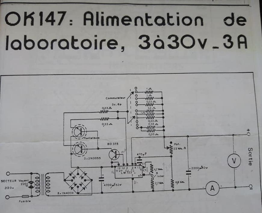
Thus, I used schemas from Electronique 3D (fr) 1, Electronics DIY 2 and from the LM723 datasheet 3.
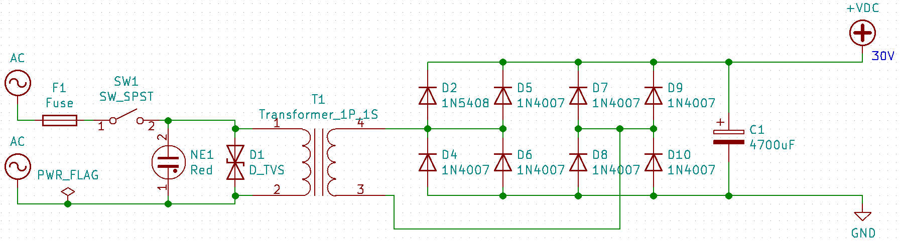
Basically, a transformer from 220 to 30V, followed by a diode bridge. I chose to use 1N5408 diodes because I had them. They are limited to 3A, my maximum. I chose to double them to be careful. I also had a big 4700µF. I included TVS in my schema despite I dont have them and did not use them, as an extra protection.
The transformer delivers 30VAC from 230VAC, it is an old transformer, now the main power is 240VAC, slightly more, the transformer now delivers 35VAC. 35VAC means $35V * \sqrt(2) = 49 V$ peak, each diode has a forward voltage of 1V and the current has to go through two of them, thus the final voltage would be 47VDC. The circuit is designed to deliver 30V max and the LM723 can not handle more than 40V. I needed to remove approximately 35 loops from the secondary of the transformer to get 30VAC from it and approximately 40 VDC after the diodes and capacitor.
The neon lamp already includes a resistor, I don’t need to add one but you might have to add a resistor if your Neon does not have one.
The fuse is a 1A (F1A 5x20), which is enough, the Power supply will be able to deliver at most 100W and should not draw more than 0.5A from the main. The initial current drawn at startup might be higher, due to the inductance part of the transformer and the big capacitors, 1A should fit.
Nothing very fancy here, lets watch the regulation part.
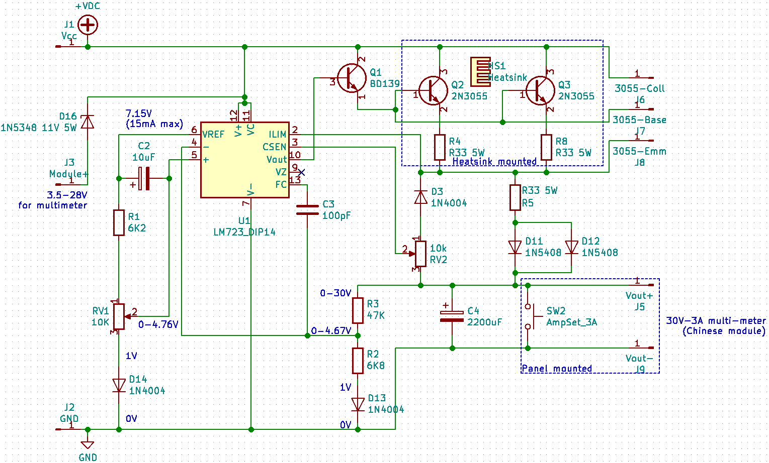
I already have 40VDC, but the Chineses multi-meter module needs between 3.5V and 28V to work. I did not have any suitable regulator, but I had some 5W Zener diodes. I used a 1N5348 11V (D16) to get $40-11 = 29V$. This is a little bit to high, but this is a theorical voltage without any load. I made this voltage available on J3 to connect the module.
I chose to use 2N3055 power transistors (Q2 and Q3) to regulate the power, they are mounted on heat sinks to dissipate the heat. I used the mica isolator, but I could remove them and add thermal paste, Each transistor has its own heat sink, not connected, and anyway, both collectors are connected. I could have more of them, but I had only two and they are enough for me. I added a ballast resistors (R4 and R8) to each emitor to compensate the difference between the transistors.
I can not drive them directly from the LM723, it can only deliver 150mA. Thus, I added a BD139 (Q1), with a small piece of metal as heatsink. It should not get very hot anyway. Thus, the LM723 can directly drive Q1, and Q1 can easily drive Q2 and Q3 (and more). I added J6, J7 and J8 pin connectors because the power transistors are not physically on the PCB.
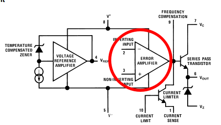
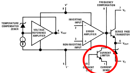
Now, I need to have a voltage regulation. I need to use pins 4, 5 and 6 from the LM723. Basically, 4 and 5 are respectively the inversed and non-inversed pins of an internal OpAmp. The datasheet says : no more than 8V between GND and pin 4 or 5, no more than 5V between 4 and 5. The LM723 provides a reference voltage of 7.15V on pin 6, but pin 6 can not deliver more than 15mA. Ok, I need to get a voltage feedback from the output to pin 4.
I used R2 and R3 to divide the output voltage and get a feedback in the LM723 specifications. I discovered that the feedback needs to be high enough to trigger the internal junction, thus I used an 1N4004 diode (D13) to have a higher low value (1V). At the end, I have a feedback between 1V and 4.67V for output between 0 and 30V.
Now, I need to have something similar for the voltage setting to feed the non-inversing input of the comparator. Thus, I used the same 1N4004 diode (D14) to increase the lower value by the same amount (1V) and calculated the voltage dividor to get between 1V and 4.77V to feed the non-inverting input of the OpAmp. The voltage divisor is calculated to limit the drawn current from pin 6 within the LM723’s datasheet specs (15mA).
Fine, I have a match between the voltage feedback and the voltage setting, they are in the LM723 specifications and should cover the whole range of values to get between 0V and 30V on output. Let’s have a look at the current limiter.
The current limiter in on pins 2 and 3 on the LM723. If the difference between pin 3 (CSEN) and pin 2 (ILIM) $ILIM-CSEN$ is positive, the LM723 will begin to reduce the output on pin 10 (Vout). But both CSEN and ILIM are internally connected to a junction and need to be both greater than the internal junction forward voltage (approx 0.6V):
I used a 0.33R 5W (R33) as a shunt to get a voltage difference proportional to the current (0-3A). With the Ohm’s law $U=R.I$, I have : \(0.33*0 <= U <= 0.33*3\), or \(0 <= U <= 1\). Nice, but I need the minimum to be greater than the internal junction, I need a diode that will accept 3A : 1N5408 support 3A, I prefer to double it and to distribute the current. Even if the current is unbalanced, at most, none will have to support 3A. At the end, the shunt has $1 <= U <= 2$. Good ! I need to get a variable fraction of it as a feedback. This is made with the variable resistor (RV2) as a voltage divisor. The value is higher enough (10K) compared to the shunt so that the current flow will be very little. I added a 1N4004 diode (no need for power here) to have the same voltage drop and to get a feedback with the same limits.
Ok, now, the current limiting feature is sized and configured.
Finally, I need a big capacitor (approx 1/10 of the source one, in theory). I used the one from the original kit : 2200µF. I connected the amp meters in serie to the output, on the negative branch, this is mandatory by design for the chinese module. I also added a momentary switch to short the output and to force the current limiter to trigger, the module shows the max current value.
Bill Of Materials - BOM
I started with the BOM and not the design, because I wanted to base my design on my available parts… Bottom-Top approach. Nevertheless, I provide here the list of components, with datasheet, manufacturer, SKU and reference at TME 4. TME is a good provider, cheap, in Europe (Poland), with fast delivery.
As I said, I reused components from my stock, I did not try these ones, you have to double check the values, refs, prices and footprints before ordering.
| Reference | Value | Quantity | Datasheet | Manufacturer | SKU | TME |
|---|---|---|---|---|---|---|
| C1 | 4700uF | 1 | https://www.tme.eu/Document/280e3fb6bfa2629e98808628203c848c/e-ls.pdf | NICHICON | LLS1J472MELA | LLS1J472MELA |
| C2 | 10uF | 1 | https://www.tme.eu/Document/ee7c1395f0741ee0ee0df84539c3fd29/e-urs.pdf | NICHICON | URS1C100MDD | URS1C100MDD |
| C3 | 100pF | 1 | https://www.tme.eu/Document/e69911e065ed5e1d0ce354af6c563ca3/CC-4.7.pdf | SR PASSIVES | CC-100 | |
| C4 | 2200uF | 1 | CE-2200/40A | |||
| D1 | D_TVS | 1 | ||||
| D13 D14 D3 | 1N4004 | 3 | http://www.vishay.com/docs/88503/1n4001.pdf | VISHAY | ||
| D16 | 1N5348 11V 5W | 1 | https://www.tme.eu/Document/01c8e2b3cf396fe61d216c295d761a68/1N53_ser.pdf | ON SEMICONDUCTOR | 1N5348BG | 1N5348BG |
| D10 D11 D12 D2 D4 D5 D6 D7 D8 D9 | 1N5408 | 10 | http://www.vishay.com/docs/88516/1n5400.pdf | VISHAY | 1N5408-E3/54 | 1N5408-E3/54 |
| F1 | Fuse | 1 | ||||
| HS1 | Heatsink | 1 | banggood.com/182x100x45mm-Aluminum-Heat-Sink-Heatsink-For-High-Power-LED-Amplifier-Transistor-Cooler-p-1142259.html | Banggood | 1142259 | |
| J1 | Vcc | 1 | ||||
| J2 | GND | 1 | ||||
| J3 | Module+ | 1 | ||||
| J5 | Vout+ | 1 | ||||
| J6 | 3055-Coll | 1 | ||||
| J7 | 3055-Base | 1 | ||||
| J8 | 3055-Emm | 1 | ||||
| J9 | Vout- | 1 | ||||
| NE1 | Red | 1 | NINIGI | NI-1RD | ||
| Q1 | BD139 | 1 | http://www.st.com/internet/com/TECHNICAL_RESOURCES/TECHNICAL_LITERATURE/DATASHEET/CD00001225.pdf | STMicroelectronics | BD139 | BD139 |
| Q2 Q3 | 2N3055 | 2 | http://www.onsemi.com/pub_link/Collateral/2N3055-D.PDF | ON SEMICONDUCTOR | 2N3055G | 2N3055G |
| R1 | 6K2 | 1 | ||||
| R2 | 6K8 | 1 | ||||
| R3 | 47K | 1 | ||||
| R4 R8 | R33 5W | 2 | ROYAL OHM | KNP05SJ033KA10 | KNP05WS-0R33 | |
| R5 | R33 5W | 1 | ROYAL OHM | KNP05SJ033KA10 | KNP05WS-0R33 | |
| RV1 RV2 | 10K | 2 | https://www.tme.eu/Document/e13a4eb615fc162fef410c3ed914459b/SR_Passives-POT2218M.pdf | SR PASSIVES | POT2218M-10K | POT2218M-10K |
| SW1 | SW_SPST | 1 | https://www.tme.eu/Document/f90695597f0f1676a8d370239f391d47/1811.1102.pdf | Marquardt | 01811.1102-02 | 1811.1102 |
| SW2 | AmpSet_3A | 1 | ||||
| T1 | 240-30-90VA | 1 | https://www.tme.eu/Document/c4aa10c935ccc8c890c2de085c552cbb/TMM-EN.pdf | BREVE TUFVASSONS | TMM63/A230/36V | TMM63/A230/36V |
| U1 | LM723_DIP14 | 1 | http://www.ti.com/lit/ds/symlink/lm723.pdf | TEXAS INSTRUMENTS | UA723CN | UA723CN |
Build
Nothing very fancy here, an old enclosure, a prototype board, a 3D printed front panel… I used XT60 connectors, Dean connectors and 3.5mm banana between the front panel, the board and the transformer. These little connectors can handle a lot of amps, they are used on drones, with 2.2A.h 35C LiPo !
I added two spare galvanometers. They are not so precise, but show very well variations, better than digital multi-meters. I have a first switch to connect the ground to the negative or positive output, or to leave the supply floating. The second switch is a momentary switch to short the output and let the maximum allowed current flow, thus I can see on the multimeter what is the max allowed current and can adjust, this switch needs to accept more than 3A. There are two 10-turns potentiometer to set the voltage and the current limits.
Tests
Turn all potentiometers to the min (check with an ohm meter). Ensure that the shortcircuit momentary switch is off. Power on, the neon should light, the galvanometers should be near 0, the digital voltage near 3V, and the digital current near 0.013A. Check the voltage on C1, should be around 40V.
If you turn the voltage potentiometer, nothing should change a lot because the current limitation is too low. Increase the current limitation by 2 or 3 turns and try the voltage limitation. It should go up. You can try the short circuit switch to check the maximum allowed current and adjust it with the current limiter.
Be careful, the current limiter can be set over 3A, but nothing is sized for that, the digital multimeter will melt, the power transistors will fry.
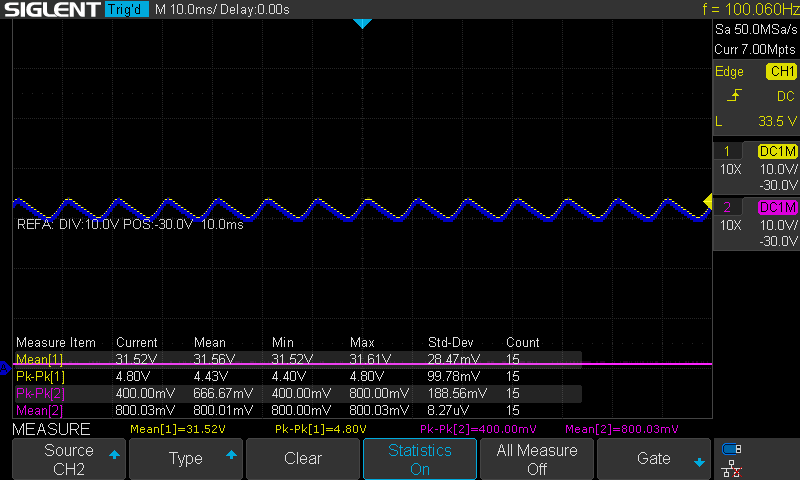
If you have an oscilloscope, you can check how much the voltage drops at C1 when you short 3A:
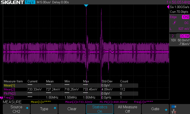
and how clean (or not) is the output current from 2 to 25V, with and without shorting:
Materials and Links
- Video
- Kicad file
- http://www.electronique-3d.fr/Le_regulateur_LM723.html
- http://electronics-diy.com/30v-10a-variable-bench-power-supply.php